A Game Boy for the modern age - Part 1
Part 1 of many: Serial Communication
What even is this about?
Around two months ago, stacksmashing posted a video about mining Bitcoin on a Game Boy. If you haven’t seen it yet, definitely check it out here! Ever since I saw that project, I was obsessed with the idea of giving my Game Boy the ability access to the web - a smart Game Boy if you will. This basically “just” involved slapping microcontroller with wifi on the Game Boys serial interface and writing a bit of code for both sides. So after cursing my poor financial decisions multiple times, I was left with around 100€ less in my bank account, and a selection of electrical components including a TTGO T-Call microcontroller (which is basically an ESP32 with SIM card support), and even more important: a Game Boy Flashcart.
This part of an ongoing series focuses on getting simple communication working between the Game Boy and the ESP32
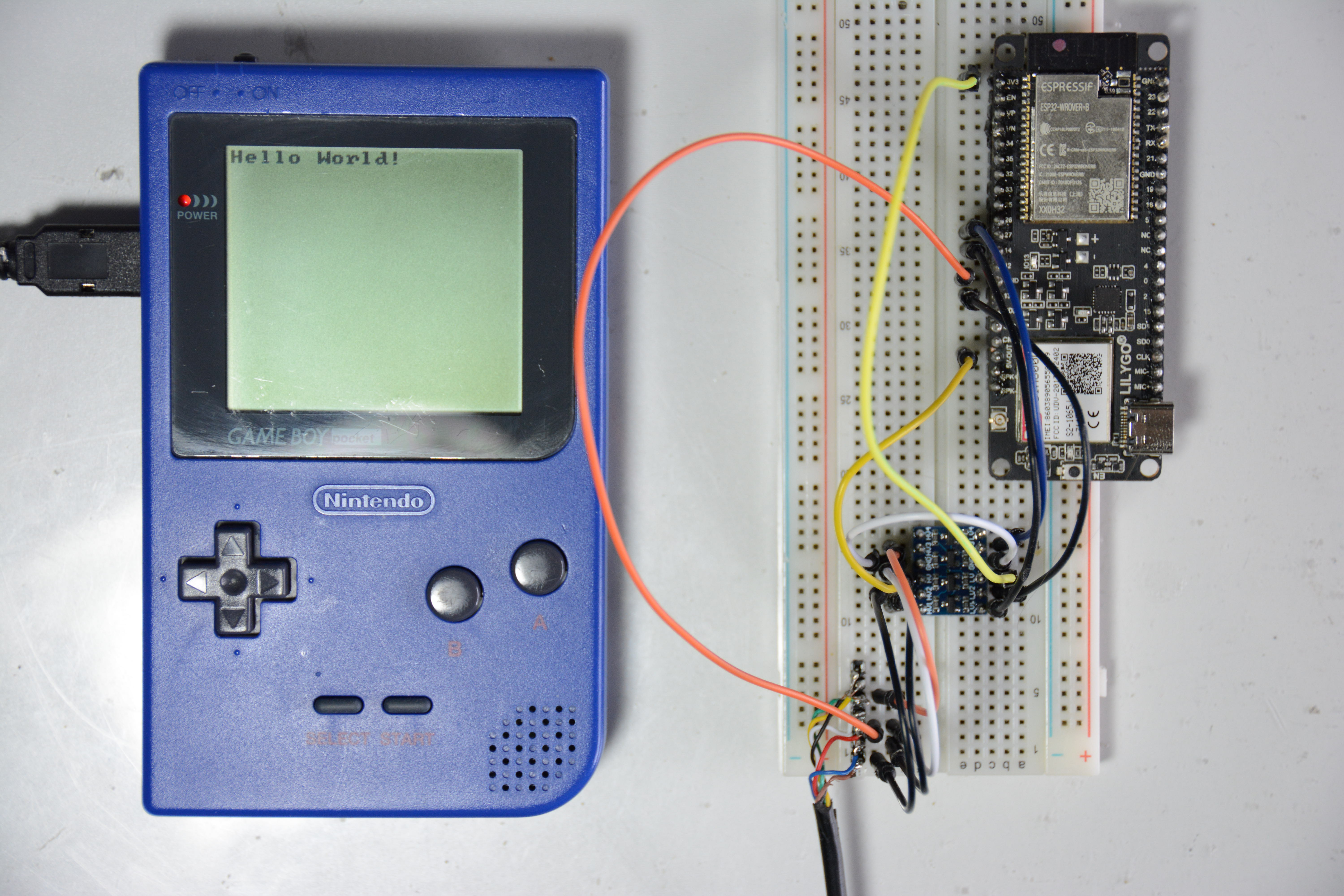
The Hardware
The Hardware setup is still fairly simple at this point. All I have is a cut up Game Boy Link cable, that is connected to the ESP32 via a 5v to 3.3v Level shifter. Because I want to power the ESP32 from the Link port alone, I am running it at the lowest possible CPU frequency of 80MHz. It draws around 10-20 mA in that configuration which seems to be around the top limit the Game Boy can supply via the Serial Port (it is obviously not built to deliver any power, so this may just kill my Game Boy, we will see…). I fear that I will run into power problems as soon as I use Wifi or similar on the ESP32.
The Software
Initially I thought getting some simple communication over serial would be quite easy - the Game Boy serial standard is quite well documented, and not very complicated at all. At the time, I was still waiting for the ESP32 to arrive, so i quickly threw together some code for the Game Boy and a random Arduino Nano I had laying around. All this code was doing is sending a simple message from the Game Boy and receiving it on the the Arduino. This worked perfectly. I basically just had to tell the Arduino that the Game Boy was a generic SPI device and it magically worked. With a good feeling, I waited patiently until the ESP32 arrived and this is where the problems began. You see, the Arduino IDE does not have an inbuilt way of using an Arduino as a SPI slave, which is why i had to do some weird direct register accesses on the Arduino Nano. When tried compiling the same code for the ESP32, it just wouldn’t work. So, I had two options:
- Just use the ESP32 as a master all the time (simple and uncomplicated)
- Reimplement the entire SPI protocol in Software, with the ability to switch between master and slave (way too overengineered)
Naturally I went with the second option. It took me a few attemps to get the receiving working, but the hard part was yet to come: sending data back to the Game Boy. I may not have mentioned this yet, but the entire Game Boy code is done in assembly. Why? Three reasons: First of, i only have 32kb of program space to work with and want to save as much space as possible. Secondly, I already made a complete Game Boy Game in assembly (https://github.com/Fisch03/Astro-Attack), so I know my way around pretty well. Third: I just really hate free time.
Armed with bgb I went into the absolute pain that is debugging on the Game Boy. Problem being that there is no way of debugging serial stuff in an emulator. I basically had to assume the hardware part and the ESP32 part was working and enter every byte manually into the bgb debugger. To no ones surprise, the hardware part wasn’t working, and neither was the ESP32. But I somehow got it working - only two weeks after the initial 3-day-timeframe I had originally given myself. I proudly present:
The IMGCP (Inter-MCU-GameBoy-Communication-Protocol)(Name not final)
Because neither the Game Boy, nor the ESP32 knows anything about the bytes it receives, I had to design some kind of protocol to signal the beginning/end of transmissions. Initially I just sent text back and fourth and used the ASCII Characters 0x02 (=Start of Text), 0x04 (=End of Transmission) and 0x06 (=Acknowledge) to section of messages. This worked fine until I realised I wanted to send more than just characters. I then started from scratch and thought about the different messages that could be transmitted. In the end I came up with this table:
| id | name | esp | gb | len | res | description |
|---|---|---|---|---|---|---|
| 00 | ping | x | search for ESP32 | |||
| 01 | ack | x | x | x | acknowledge that a message has been received | |
| 02 | req | x | x | request some form of data | ||
| 03 | res | x | x | x | response to any request | |
| 04 | stat | x | wifi + co. status updates | |||
| 05 | msg | x | x | request pop up message on the Game Boy |
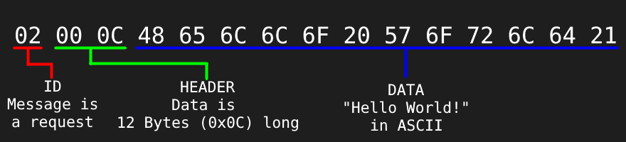
What does that mean? The first two columns just list the unique ID and the name of a message. The next two columns indicate whether a message can be sent either by the ESP32 or the Game Boy (or both). If the next column is ticked, the message has a variable length and finally, if the last column is ticked, the message will only be sent as a response to another message. Having this, a message consists of (up to) three parts:
- ID: One Byte containing the ID of the message
- Header: Two Bytes containing the length of the message (only if the message has a variable length)
- Data: 0-64KiB of Data (a ping for example contains no data)
For example, a request with the contents of “Hello World!” would look like this:
Sending/Receiving messages on the Gameboy
The Gameboy handles Serial in a straightforward, but hard to work with way. As soon as a byte is sent or received, the serial interrupt gets triggered. That means I had to implement some sort of queue system to keep track of the current serial operation. I divided each serial communication into five fundamental blocks:
- Send the Header of a Message
- Send the Data of a Message
- Wait for acknowlegdement
- Receive the Header of a Message
- Receive the Data of a Message
Whenever a serial interrupt is triggered, the Game Boy goes through these blocks from top to bottom and checks if it is queued. This means that the order is always the same, just that some elements may be left out. Continuing the above example, a request sent from the Gameboy would cause all five blocks to be queued, because the request has a header and data, waits for an acknowledgement and receives a returning header and data.
A few things are important to note here:
- The received message does not contain an ID to save up on the Game Boys resources. If the Game Boy request something, it is a given that the next received message is a response. Because of that, the ID is omitted.
- There is no need to queue up the sending of an ID, because an interrupt is only triggered after a byte is received. The ID is the first thing that is sent and thus no interrupt will be triggered.
- If an interrupt is triggered and nothing is currently queued up, we know that a transfer has been initiated by the ESP32.
This queue together with some other important flags is stored in a single byte in ram.
The Verdict
While some dumb design decisions were definitely made, I am still pretty proud of the results so far. From now on things should progress a bit smoother because the non-debuggable stuff is mostly done. Next thing I will try to do is actually fetching some data from the internet, so look forward to that! See you next time!